The GTL Technology
Pyrolysis of Renewables:
Some technologies rely on a gasification process utilizing an up-draft or down-draft gasifier. The up-draft gasifier, the renewable feedstock or fuel, flows downward against rising air, internally combustion-heating the renewable feedstock. The combustion fuel is largely tar formed from the feed. This process is not efficient for making synthetic fuels because the synthesis gas produced has a Ratio of H2/CO = 1.0, whereas a Ratio of 2.0 is required. Also, the gas contains a high level of CO2 and nitrogen diluent.
The Polyfuel Group Limited process is true pyrolysis: the renewable feedstock is fed to the externally heated retort. It is supplied with heat by some of the excess hydrogen gas from the process. This fuel is circa 15% of the excess hydrogen gas produced. The extremely high temperatures in the vessels decompose the renewable feed into small molecules, mainly water, hydrogen, carbon monoxide, carbon dioxide and nitrogen.
A H₂/CO Ratio of 2.0 is achieved, which is ideal for making synthetic fuel.
Fischer Tropsch (FT) Conversion of synthesis gas to fuels
Traditional FT converts the synthesis gas into n-paraffins (straight-chain), with liquids having molecules having between 2 and 60 carbon atoms. Typically, 45 weight per cent of the liquids have greater than 20 carbons per molecule and are classified as wax. The FT product is then converted with catalyst, high pressure, and high temperature mainly into C5-C10 paraffin (naphtha) and C11-C20 paraffin (diesel).
The Polyfuel Group Technology process does not need a hydrocracker since the direct FT product already consists only of the desired naphtha and diesel molecules and zero wax molecules. This makes the Polyfuel process more economical since it eliminates the expensive hydrocracker and ancillary equipment.
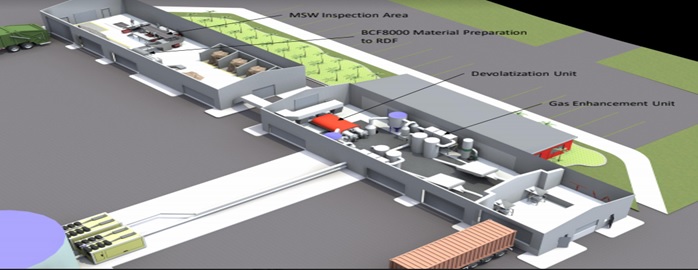
- The infeed system:
The infeed system burners (for indirect heating) and control systems, for speed, temperature control, instantaneous gas constituent monitoring via multi-channel Mass Spectrometer for feedback to the front-end control system. - Front-end Devitalization Process: conveyers send granular feedstock to the front-end unit for devolatilization.
- Proprietary Gas enhancement Module: This section ensures that the tars and heavy hydrocarbons are decomposed.
1. The infeed system-Front end Preparation and Gasification process
While every feedstock may differ, all feedstocks require.
(1) Proper time (Dwell) within the process for complete conversion.
(2) Correct Temperature for the particular series of feedstock material and desired gas output.
(3) Turbulence inside the heated retort to assure all materials have the correct exposure and the proper Surface Temperatures over the desired time (Dwell).
The front-end gasification technology is a modular system designed for continuous feed. The technology is very safe as it operates under atmospheric pressure. This freshly prepared technology is very tolerant of various wastes and poor waste conditions such as moisture. The process outputs are Synthesis Gas with a H2/CO ratio of 2.0 and a semi-activated carbon product.
Please take note that this is a miniature petrochemical thermal process. Any petrochemical process requires steady-state conditions to be efficient. We can maintain steady-state processing, no matter the waste stream using the pre-processing technology to prepare any feedstock into a granular feedstock to help eliminate feedstock issues.

The developers recognized early in our technology development that varying moisture content and varying particle size will not allow steady-state processing. Inconsistent feedstock (both moisture and density) were substantial contributors to NON-steady state pyrolytic operations. Further, excess moisture (H20) required additional parasitic energy to the system. It resulted in higher amounts of CO2 in the resultant gas due to excess H20. To this end, we added pre-processing to the technology, which can process any waste material of any moisture level. Once the material to be processed is loaded into the pre-processor, it is mixed/masticated and heated in a slight vacuum to remove moisture. The temperatures are adjusted to ensure the destruction of any pathogens or viruses if required. This processed material is granulated at the end of the processing yielding a consistent size and moisture content feedstock, allowing for compatible steady-state processing.
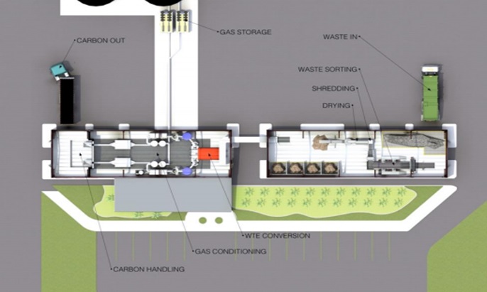
2. Proprietary Gas enhancement Module
Material enters the auger/retort area of the unit. Specially designed auger flights assure all feedstock particles are exposed to the correct process temperature and surfaces so that all material converts to gas and semi-activated carbon.
Once all the feedstocks are converted to gas and carbon. The carbon travel to the next destination in the process. The carbon then enters the cooling system to reduce its temperature permitting safe packing in FIBCs (flexible individual bulk containers), known as 1-tonne bags. The carbon can then be sold or sent for upgrading.
The gas from the process, while still at process temperature, travels to the Gas Enhancement Module. Other systems do not correctly handle the hot gases at this point, causing tars, unstable oils downstream and causing problems with the equipment and oil later in the process.When the hot gas enters the first vessel of the gas Enhancement Module, it immediately encounters a specially prepared media that begins to break down the long-chain hydrocarbons, which, if untreated, can cause tars and waxes. The long-chain need to become short-chain hydrocarbons CH4, some Hydrogen H2 and some Carbon structures, including carbon monoxide.
The next module in the gas train is configured to direct the gas formation to higher Methane CH4 gas or a true Synthesis gas of 2-H2 and Carbon Monoxide 1-CO. The latter is ideally suited for the smooth performance of multiple manufacturers Engine Gen Sets should the desired output be electricity or a Fischer Tropsch plant if the desired product is liquid motor fuels.
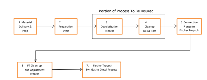
Description of steps.
- Material Delivery & Prep: MSW is presented to the tipping floor, then loaded on a conveyor to the sorting line. After sorting, the primary shredding reduces the material to sub 152 mm square.
- Material Preparation Cycle: Shredded material is conveyed to the pre-processor conditioner, where it is masticated and dewatered to less than 5% moisture and converted to a Granular Feedstock.
- Front-end Devitalization Process: Conveyors carry the granular feedstock to the front-end unit for devolatilization.
- High-Temperature Gas Enhancement Module: the gas enhancement module is the first step in cleaning up the tars and oils present in the gas. The long-chain hydrocarbons are now thermally broken into an array of hydrocarbon gases. In this process, gas-treated using this method is stabilized, preventing oxidation and removing any tars present in the finished gas.
- Gas clean-up: A sacrificial bed removes the H2
- Syngas adjustment: Entrained methane and higher hydrocarbons will be converted to synthesis gas using the inherent heat of the gas (900 ºC.). A portion of the CO2 will be converted to CO to provide a higher liquid yield. The proper H2/CO ratio will be ensured at this point.
- Syngas cooling: The syngas will be cooled with a water quench, recovering steam and providing an additional safeguard against acidic species and residual tars.
Connection Flange to FT (Fisher Tropsch) technology: This is the measurement point of the gas volume as it is handed off to the GTL Unit. Gas Volume will be the unit of measure to guarantee the success of the process.
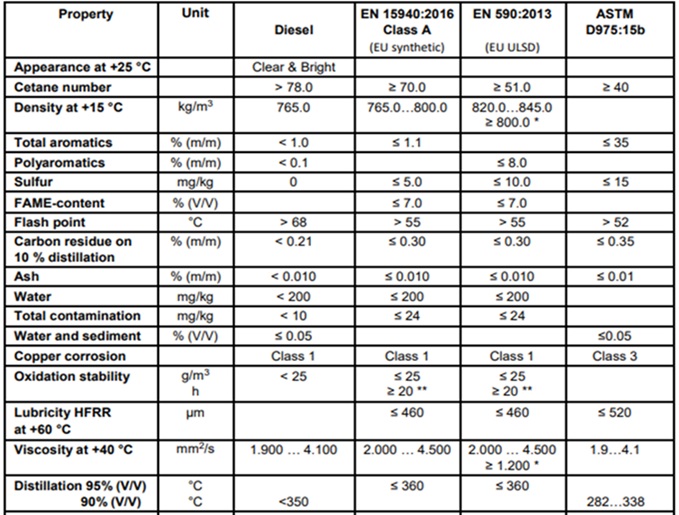
Fuel test results datasheet
Ease of Use
In general, GTL Fuel can be packaged, transported, and stored using the same equipment, materials, and procedures as conventional diesel. Diesel vehicles can also run on GTL Fuel without engine or exhaust system modifications, which means that GTL Fuel is a drop-in replacement for traditional diesel, allowing seamless introduction without investment in new vehicles or refuelling infrastructure. GTL fuel is also very often used as blending stock because mixing it with conventional petroleum diesel helps to lower the overall quantity of pollutants by dilution.
Product Characteristics
GTL Fuel is a premium quality product. Although it has broadly similar physical characteristics to conventional diesel, it has a much higher cetane number, higher mass calorific value, zero sulphur and aromatics, and a lower density. GTL Fuel is almost entirely paraffinic and comprises hydrocarbon molecules of essentially only two types, normal paraffin and iso-paraffins. It is essentially free from unsaturated molecules, such as olefins (alkenes) and aromatics, which are present in conventional fuels. These unique properties enable more efficient combustion and lower vehicle local emissions. GTL Fuel can meet the needs of most temperate and cold climates. It is Cold Filter Plugging Point (CFPP) is typically in the range of -9°C to -20°C, depending on the requirements of the environment. Lower CFPP batches have also been produced. Because of high Cetane values, vehicles start easier and run more smoothly.
Successful World-wide Experience:
In the past decade, Shell has conducted many field trials of GTL Fuel in major cities worldwide. These vehicle trials have tested the performance of GTL Fuel over many months of actual “on the road” conditions. The trials showed that the switchover from conventional diesel was easy and vehicle performance was maintained or improved. They have also helped raise awareness of GTL fuel amongst governments, automotive manufacturers, and the public in Europe, the USA, and Asia. Finally, given that the world’s largest GTL plant is Shell’s Pearl plant in Doha, Qatar Airways has also demonstrated the use of GTL aviation fuel from that plant in its aircraft.
Edward Mooney sits on the board of the Organized Private Sector Investors Association Of Africa Special Economic Zones as the assistant chair